

Last week I released version 2.0 of my open-source drag-and-drop quantum circuit simulator Quirk.
![]()
In this post, in addition to the breaking changes that prompted bumping the major version, I want to talk about events and improvements in the year since the previous post.
Recognition
I really do think that, at least within the niche of "learning by interacting", Quirk wipes the floor with anything else out there right now. But... I would be exaggerating if I said Quirk has reached a significant number of the people who could actually make use of it.
A handful of professors and "code camp" runners have contacted me about plans to use Quirk for teaching, but only a handful. So if you're interested in using Quirk for teaching, or know someone who would be, or are using it and have noticed something problematic for students, please let me know.
I have heard some nice remarks about Quirk from quantum computing researchers. Michael Nielsen called Quirk "great fun". Dave Bacon referred to Quirk as "the most beautiful quantum circuit simulator ever". And Scott Aaronson noted that Quirk "looks fantastic!!". (These are off the cuff remarks, not endorsements.)
On a more personal level, the fact that I wrote Quirk got me contacted by two separate quantum computing startups. It opened a lot of doors. I also used Quirk in finding an ever-so-slightly-more-compact construction for Shor's algorithm, which I intend to turn into a paper.
Okay, enough of this blatant self-aggrandizing stuff. On to the actual changes.
Breaking Changes
Unusually for software, none of the breaking changes I made affect how circuits behave. Any circuits you've bookmarked will still load and give the same results. What's different is how the results are displayed.
Spherical Coordinate Changes
When I was first designing Quirk, I made a lot of arbitrary decisions. In particular, in the Bloch sphere display, qubits that are On have to point along some direction. What should that direction be?

I figured that the natural direction for "onward" was upward, with offward correspondingly downward. Secondarily, I decided that the $X$-axis states (i.e. $|0\rangle+|1\rangle$ and $|0\rangle - |1\rangle$) should point leftward/rightward, since why would you ever not have an $X$-axis going left to right? That left the $Y$-axis going foward/backward, the most awkward draw direction, which was fine by me since quantum information theorists have some kind of vendetta against $Y$. They use $X \cdot Z$ instead. So, until last week, Z-up X-right Y-back with Off=-1 and On=+1 was the convention Quirk used.
The problem, of course, is that the quantum information and physics communities don't follow what I thought of as the "obvious" convention. Their convention disagrees with basically all of my choices (except for right-handedness). Physicists like to point Off upward (...what) and to point the X axis towards the user (...what?!).
Another source of disagreement was the latitude $\phi$. Me, mathematicians, and globe-makers range $\phi$ from $-90^\circ$ to $+90^\circ$ with zero at the XY equator. Physicists instead range $\phi$ from $0^\circ$ to $180^\circ$ with $0$ at the top pole.
I can't really say I agree with the physicists' conventions, but... Well, Quirk's raison d'être is to be a useful learning tool. And I've received emails from professors who want to use Quirk in their courses, except the difference in conventions w.r.t. textbooks is a problem for them. How can I say no to that?
I'd rather agree with the other material students have than force them to do error-prone coordinate conversions. So "Offward and upward!" I say, with only a slight gritting of teeth. Quirk's bloch spheres are now oriented the same as the one on Wikipedia: Z-up X-front Y-right with Off=+1 and On=-1.

It bothers me that this convention makes it harder to gauge what Hadamard gates are doing, but the consistency is worth it. And I do like that now On states are negative and Off states positive because, given $s=0$ for Off and $s=1$ for On, the rule "head towards $(-1)^s$" feels right.
Control Symbol Changes
The second big breaking change for v2 is how $X$-axis and $Y$-axis controls are drawn.
Originally, I picked the symbols for the $X$-axis controls based on the state they affected. I used a circled-plus $\oplus$ for the one that matched the "$X$-Off" state $|0\rangle + |1\rangle$, and a circled-minus $\ominus$ for the one that matched the "$X$-On" state $|0\rangle - |1\rangle$. Plus for the state with a plus and minus for the state with a minus.
The problem with that choice of notation is that, as I mentioned in Thinking of Operations as Controls, an $X$-gate is like a control that matches the $X$-On state. When you have an $X$-gate controlled by an $X$-On control, you can exchange the gate for the control without affecting behavior. But the $X$-gate is drawn as a circled-plus, not a circled-minus, so the $X$-gate used to look like the control it couldn't exchange with. That's a notation disaster!
So I switched the symbols. Now I use $\oplus$ for the control that matches the $X$-On state $|0\rangle - |1\rangle$, and $\ominus$ for its partner. Additionally, since "two lines" means On for $X$ now, and "agree on lines-vs-on" is how I picked which $Y$-axis control got $\otimes$ vs $\oslash$, preserving the rule means a switch of the $X$ symbols forces a switch of the $Y$ symbols. So I now use $\otimes$ for the $Y$-On control (matches $|0\rangle + i|1\rangle$) and $\oslash$ for the $Y$-Off control.
... To be honest, I'm a bit worried this will end up being a bad decision. The symbol switch forced a corresponding change in the notation on my post-selection gates. Now the gate $|+\rangle \langle + |$ keeps the state matched by the $\oplus$ control, namely $|0\rangle - |1\rangle$. But in papers the symbol $|+\rangle$ is often used as a shorthand for the state $|0\rangle + |1\rangle$. Urgh.
Maybe a year from now I'll have changed the control symbols to something completely different, or never draw X gates as big circled pluses, just to avoid the issue entirely. But for now, we're going with what it is.
Endianness Changes
The final change prompting a version bump is the endianness of kets. (Well... actually, I switched this in the jump from v1.8 to v1.9. Whoops. So much for proper semantic versioning.)
When you sweep your mouse over displays that enumerate states, i.e. the chance, amplitude, and density displays, the states now count like $|00..00\rangle$, $|00..01\rangle$, $|00..10\rangle$, $|00..11\rangle$, etc. They used to count like $|00..00\rangle$, $|10..00\rangle$, etc. Same states, different labels.
In other words, kets are now big-endian. They have the 'big bit' first, analogous to how decimal notation puts the 'big digit' first (15 is fifteen, not fifty one). Big-endian is what people naturally expect.
Improvements
If I listed all the improvements since last year's post (i.e. since v1.4), this post would turn into a very long very boring list. So I'll try to focus on just the big stuff.
The most relevant-to-users change is that there's a lot more arithmetic gates. Addition, multiplication, comparison, modular exponentiation, and various other goodies that are tedious to build out of basic gates are now included out of the box. Also, arithmetic gates started off very clunky because I was packaging the input and output sections into the same gate. Arithmetic is a lot more convenient now that "Input Gates" have been factored out into their own thing.
As an example, the modular arithmetic gates make simulating Shor's algorithm very compact (in width, not height; the qubit limit hurts here):
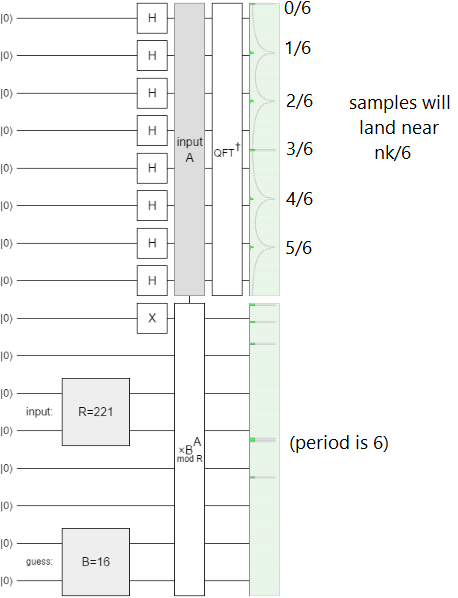
Other new gates include the X/Y axis controls and post-selection gates, wire-rearranging gates like left-rotate and interleave, and the parametrized X/Y/Z gates. Great for making circuits more compact and elegant.
Another big change that happened over the last year was the introduction of custom gates. Click the "make gate" button, and you can define a gate in terms of a specified rotation, matrix, or section of the current circuit. In fact, because custom gates can contain arithmetic gates and the inputs to those arithmetic gates can come from the external circuit, custom gates can be parametrized; they're functions!
A more minor change is the addition of an intro menu. New users aren't dumped into the middle of the program with no context on what the heck just happened anymore. The menu has links to example circuits, the source code, and a tutorial video (which is currently out of date, and the first video I've ever made, so not particularly great).
Something users might notice, unconsciously, is that Quirk's performance has improved since last year. The size of Quirk's minified code has more than doubled (bleh), but the time it takes to simulate and draw a short 16 qubit circuit has been cut from ~150ms to ~50ms (on my machine, in Chrome). Game programmers will laugh out loud at 20fps, but it's a nice step up from 7fps. (Of course performance is much better with fewer qubits. On circuits with 10 qubits the redraws take ~16ms.)
The last thing I'll mention is that lots of little visual details have been added. Some were minor, like adding shadows under toolbox gates so they "pop out" more, shading dynamic gates yellow, and squishing their rotation-indicators to look like rotations around the appropriate axis. Others were major, like adding a dashed vertical line to non-local operations such as post-selection, showing per-column and whole-circuit survival rates, and having amplitude gates switch to a "fixed phase" mode when the local phases became ambiguous. And some visual changes were in between, like cutting single-qubit density matrix displays out of the default displays at the end of every circuit (because they were less informative and less readable than the bloch sphere displays).
If you want way more details, read the releases tab on github.
Dev Improvements
Quirk didn't just add user features, it also add features for me, the developer.
Case in point, I used to write every gate shader in full by hand. Each shader did its own special thing to handle controls and the tensor/bitwise structure of gates' effects. Nowadays the bulk of the shaders is all generated by code, and only the important details are specified by hand. This was a crucial part of getting Quirk to work on iPhones without sacrificing speed on desktops, but it's also damn convenient.
For example, the shader for the increment and decrement gates used to be 20 finicky lines long; now it's nearly a one-liner:
let offsetShader = ketShaderPermute(
    'uniform float amount;',
    'return mod(out_id - amount + span, span);');
Another big improvement is testing. It's hard for me to communicate how much nicer Quirk's testing story has gotten. There used to be dozens and dozens of lines of boilerplate around gate tests, carefully setting up input pixel data to feed into a shader, circuits defined by giant transposed arrays of long gate names, eclectic comparisons of the results against redundant computation performed using matrices, and on and on. Now that's all done automatically to every single gate with a single test.
Part of building a gate is specifying the matrix or permutation its shader is supposed to be implementing, and the test just iterates over every known gate comparing the shader's behavior against the specified behavior using random test vectors. In effect, what used to be boilerplate test code is now hidden inside stuff I was specifying anyways:
ModularAdditionGates.PlusAModRFamily = Gate.buildFamily(1, 16, (span, builder) => builder.
    setSerializedId("+AmodR" + span).
    [...]
    /////// THIS NEXT LINE DOUBLES AS TEST CODE ///////
    setKnownEffectToParametrizedPermutation((t, a, r) => t < r ? (t + a) % r : t));
The build-up of testing utility methods for specifying and evaluating circuits has also made more focused tests easier to write. For example, when I found a circuit that triggered a precision bug in large multiplications, the repro test ended up as basically just the circuit in text form:
    let circuit = CircuitDefinition.fromTextDiagram(new Map([
        ['a', Gates.InputGates.SetA.withParam(16385)],
        ['*', Gates.MultiplicationGates.TimesAFamily],
        ['X', Gates.HalfTurns.X],
        ['-', undefined],
        ['/', null]]),
        `-a-X-*-
         -----/-
         -----/-
         -----/-
         -----/-
         -----/-
         -----/-
         -----/-
         -----/-
         -----/-
         -----/-
         -----/-
         -----/-
         ---X-/-
         -----/-
         -----/-`);
    assertThatCircuitOutputsBasisKet(circuit, 24577);
There is still some boilerplate, but the majority of the test is actually important details.
I've also adopted functional reactive programming to drive the UI elements, added support for performance tests, introduced focused mutability to improve speed, used draw caching to improve speed, replaced generators with raw for loops on hot paths to improve speed, etc, etc, etc. Listing minor dev changes is even more boring than listing minor user changes, so I'll stop here.
Summary
Quirk has improved over the last year. The display conventions for bloch spheres, controls, and kets changed, prompting a major version bump. More people should use Quirk as a resource when teaching quantum computation.
