

In this post: an interactive quantum circuit inspector written in javascript, and an explanation of how to solve its 'Fourier' puzzle.
Tactics
Every time I write about quantum computing, I try to take a different approach to explaining it.
- Grover's Quantum Search Algorithm used a bottom-up approach: discussing fundamental pieces, how to combine them, and building on that until it searched for things.
- Implementing Quantum Pseudo-Telepathy explained things from the top down, by starting from the solution and breaking it into pieces until we hit math.
- What Quantum Computers do Faster, with Caveats tried to keep things short. It gave information about the mechanism that quantum computers are exploiting, and little else.
This post's tactic is interactive puzzle solving.
Quantum Circuit Inspector
Below is an interactive quantum circuit inspector, with some puzzles. The rest of this posts spoils the hardest puzzle, so give it a try before reading on. The goal is to drag gates onto the circuit to transform the given inputs into the desired outputs. You can switch between a few different puzzles.
(Hover your cursor over things to see descriptions and hints.)
If you want to submit your own puzzles, feel free to send a pull request to the quantum circuit inspector's github repo. (There's also a lot of other things that could be improved, like the UX and general code cleanliness. You can try things out in the jsFiddle.)
The Fourier Transform
Classical computers can compute a Fourier Transform, determining what frequencies generate some given data, in $O(n \cdot \log{n})$ time using the Fast Fourier Transform algorithm. The Fourier transform is a surprisingly versatile operation, so being able to compute it quickly is very important.
The Quantum Fourier Transform (QFT) is a Fourier transform algorithm that runs on quantum computers, and is exponentially faster than the classical algorithm when you can use it. It does have some serious limitations: preparing the input state may not be possible or tractable, and you can only sample the output (which is why sometimes the QFT is called Quantum Fourier Sampling).
Assuming you can prepare a useful input and process the output into a desired answer, like Shor's Quantum Factoring Algorithm does, the QFT requires only $O(log^2{n})$ operations to Fourier transform a quantum computer's superposition.
Making a Fourier Transform Circuit
The hardest puzzle in the quantum circuit inspector, near the top of the post, tasks you with making your own QFT circuit. I am going to spoil that puzzle by explaining how to do it.
The puzzle provides eight inputs to test the circuit with. Each test input is a different frequency, with its superposition phasing by $\frac{i}{8}$ turns per state. Each test input is associated with a desired output: just state $i$, the index of the input frequency. Our goal is to find some sequence of gates that turns the test inputs into the desired outputs.
The first step to solving the puzzle, assuming you don't just start fiddling with gates (also a viable strategy), is noticing an important pattern present in the inputs. Look at the amplitudes for states that are $4$ apart:
Do you see it? After $4$ turns of $\frac{i}{8}$, the resulting state is always exactly equal or exactly opposite.
Why is that useful? Because a Hadamard gate will factor out that pattern (it has exactly the same sort of regularity). Inserting an H gate on bit 2 (because $2^2 = 4$ and the pattern is $4$ apart) will make things simpler:

The above animation is showing that a Hadamard gate on bit 2 gets us closer to our goal. We want each input frequency to end up as a single output, and after the H gate they're in four states instead of eight. Half way there!
It's tempting to try to apply the same trick to bit 1, but it doesn't quite work:
Do you see the problem? Although the top four rows have the 'opposite or equal' property (but spaced by $2$ instead of $4$), the bottom four rows don't. The bottom two rows are off by 90°.
The bottom two rows are at offsets 6 and 7, which is 110 and 111 in binary. They are the states where bit 1 and bit 2 are both ON. We want to make the phases of these states rotate by 90°. The R(-90°) phase shift gate almost does what we want, but it is only conditional on a single bit. We make it conditional on both by setting the other bit's wire as a control for the operation.
With the 90° fix-up in place, putting a Hadamard gate on bit 1 will factor out another half the junk:
And now the pattern is clear for what needs to be done for the last bit. We'll use phase shift gates to ensure the two remaining non-empty states in each column have equal or opposite amplitudes, then Hadamard it. As a result, each frequency input ends up in a single unique output state.
Great!... except they're the wrong states:
We want a nice diagonal line, but right now things look more like a circle.
The problem is that doing a QFT has a tendency to reverse our bits. Sometimes you can get away with ignoring this, but it's useful to know how to fix it. All we need to do is swap bit0 and bit2 to get the outputs in the proper order (just apply the solution of the 'swap' puzzle).
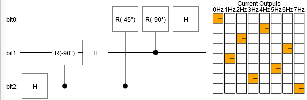
The resulting circuit is a QFT over three bits:
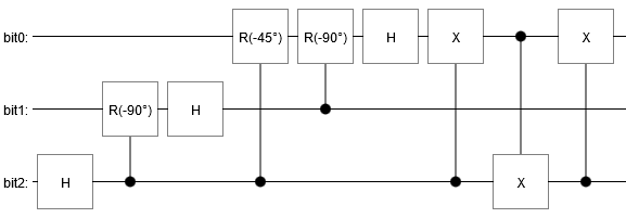
Of course that's not the only solution. For example, you could also swap the bits beforehand. A slight re-arrangement of the gates, and you get the circuit I used for the QFT animation from last time:
You might worry that our QFT circuit won't work on combinations of frequencies, because we only tested single frequencies. Fortunately, quantum circuits always implement linear operations. That means scaling an input will scale the output, and adding inputs will add outputs. Handling combinations of inputs is free built-in functionality.
I hope this has given a little insight into how you go about making a quantum circuit.
Summary
A Quantum Fourier Transform is just a bunch of Hadamard gates with some phase corrections along the way, and a bit reversal thrown in if necessary.
