

This is a followup to a post from last year, "A Slightly Smaller Surface Code S Gate", where I showed that the S gate construction from here could be simplified by replacing a Hadamard operation with a Pauli operation. (It's better because Hadamards need spacetime volume, but Paulis don't.)
In this post I'm going to discuss another optimization to that circuit. This optimization will reduce the size by another 33%, enough to make it a mere... errr... four times as large as state-of-the-art constructions..?
Let's go!
Circuit Diagrams vs Braiding Diagrams
One of the interesting things about working in the surface code is that circuit diagrams get converted into a very different form: braiding diagrams. A braiding diagram is, at its core, just a plan for where and when to turn off various physical qubits. When you turn off a chunk of qubits, this creates a defect in the otherwise perfect surface. Each defect you introduce creates a degree of freedom. You can encode qubits into those degrees of freedom, operate on the encoded qubits by moving the defects around, and measure the encoded qubits by destroying the defects.
Although braiding diagrams and circuit diagrams both represent the same thing (a quantum computation), the kinds of optimizations you apply to them feel very different. For example, braiding diagrams are inherently topological in a way that doesn't care that much about whether a braid is travelling in a spacelike or timelike direction. You can take a braid-based computation spread out over a long time and literally just "tip it over" so that the computation is instead spread over a lot of space. You can even flip the braid-based computation completely around, so that the forward direction of the computation is actually pointing backward in time! (To be fair, that doesn't work on anything involving a logical measurement, which is kind of a lot of things, but it's still a very powerful technique.)
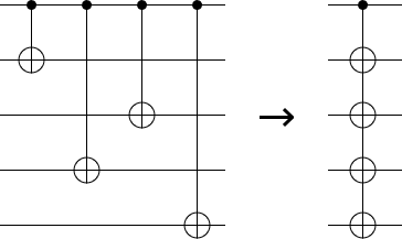
One kind of optimization that is relevant to this post, and is natural in both braiding diagrams and circuit diagrams, is combining CNOT operations. When multiple adjacent CNOTs all have a common control, they can be merged into a single controlled multi-target operation.
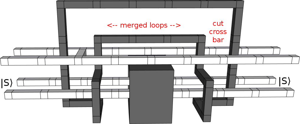
In a circuit diagram, merging CNOTS looks like this:
Whereas in a braiding diagram merging CNOTs looks like this:
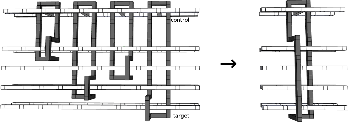
Basically, if you look at a braiding diagram and see two instances of "black loop going around white crossbar" right next to each other, you can combine the two into a single black loop going around a single white crossbar.
Which brings us back to the S gate construction.
Optimizing S Gates Across Time
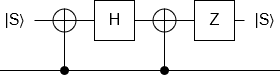
Here is the S gate circuit from last time:
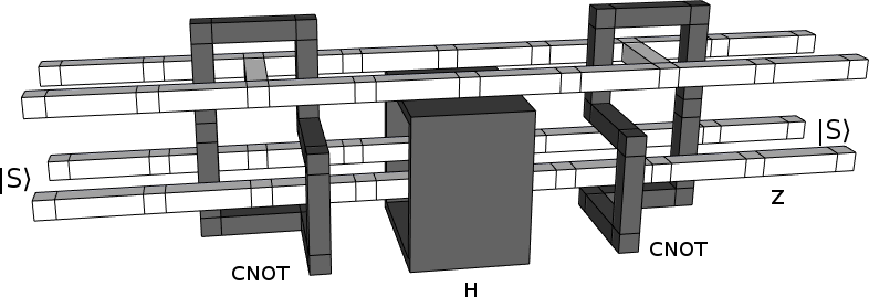
And here is a braiding diagram representing the same circuit (but flipped upside down):
Do you see it?
The opportunity?
Here, I'll highlight it:
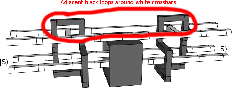
There's two instances of a black loop around a white crossbar, and they are right next to each other. It might look like that black box is in the way, but topologically speaking there's nothing preventing the tops of the two loops from being pulled together.
Still... surely we can't combine these particular loops? I mean, the optimization made sense when the loops corresponded to CNOTs onto independent qubits, but this is two CNOTs onto the same qubit at different points in time. If you were to draw a circuit diagram of what we're planning to do, it just kind of looks ridiculous:
But, you know what? Let's throw caution to the wind and see what happens.
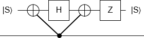
We merge the two loops:
Now, although things look a bit tight, it's possible to temporarily shrink the handle in the middle and pull it out through the gap between the box and the top white poles. Topology is great like that.
(Interestingly, this only works because the two CNOTs started of as mirror images of each other. If I'd started with CNOTs of the same chirality, the "handle" would have been wrapped around the bottom front white pole and I'd never have noticed it was possible to simplify things.)
Anyways, pull the handle out:
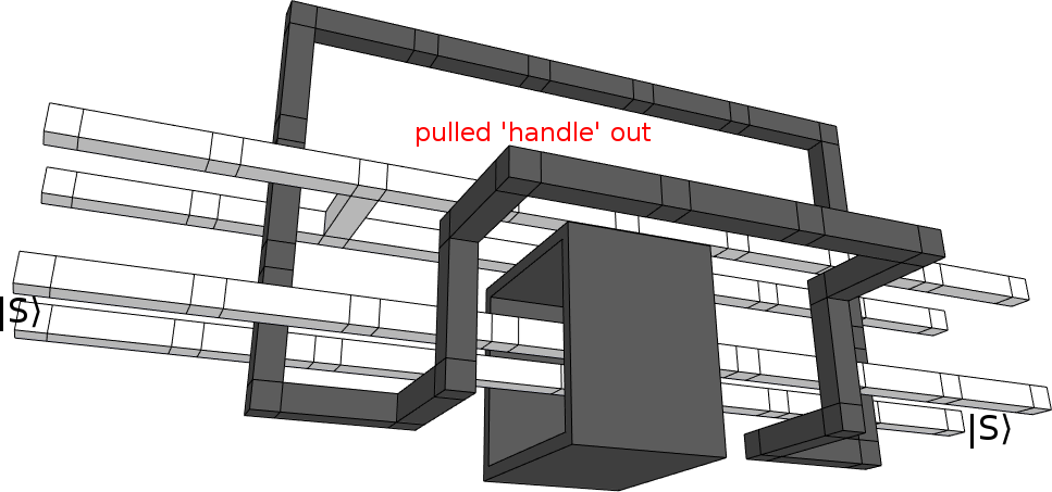
Now we're just going to tighten everything up. Center the crossbar, tuck the black loop under the black box, flatten the black loop into a single layer, then pull everything snug:
This is normally where I'd stop. But if you're feeling particularly adventurous, you can apply an optimization called "bridge compression" to kinda melt the black loop into the Hadamard box:
No guarantees on that last one. Regardless, even if we don't do the bridge compression, this new construction is smaller than the old one. We started with something that covered roughly 30 unit cells, and now we have something that covers roughly 20 unit cells.
In order to check if the construction is correct, it is necessary to check the "correlation surfaces" it implies. Basically, you imagine there's a plane between each pair of white poles (or a cylinder around one of them), and there are rules for how the surface of the plane (or cylinder) can be extended (e.g. white correlation surfaces can't pass through black defects). If two braiding diagrams cause the same input surfaces to produce the same output surfaces, then the two constructions should be equivalent.
As far as I can tell, this construction produces the same correlation surfaces as the original one. I haven't checked it in detail, so who knows, but it passes a cursory check.
State of the Art
That brings us to the elephant in the room. Why does the title of this post say "larger" instead of "smaller"? And why isn't this a fun little preprint on the arXiv?
Well... it turns out there are even better ways of doing S gates. Specifically, there is a technique based on so-called "twists". See the paper "Poking holes and cutting corners to achieve Clifford gates with the surface code" by Brown et al.
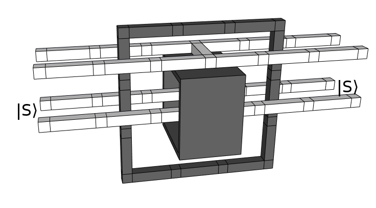
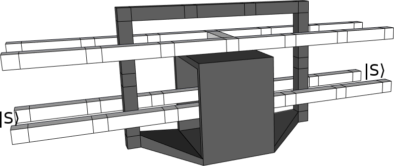
I can't say I understand how that all works yet, but basically it involves temporarily converting the double-defect qubits I've been using into a more compact representation that makes some operations easier. If you were to make a braiding diagram of it then that diagram would essentially look like this:
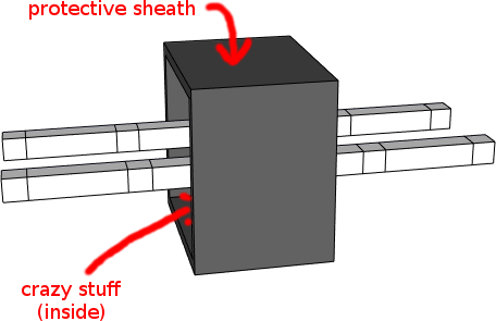
(All the fun stuff is hidden behind the black box, which is protecting the surrounding volume from the twisty nonsense happening within.)
One notes that the above diagram uses, like, way less volume than any of the diagrams of my construction. Also, it only has one pair of white poles instead of two pairs of white poles. They didn't even need an ancilla qubit! As a result, their construction easily uses four times less volume than mine.
It's kind of hard to describe the feeling of "Oh wow I made my thing better!" mixed with "Huh. My thing is not nearly as good as that thing.". Satisfying, not unpleasant, motivating, yet lacking.
Closing Remarks
Braiding diagrams allow for optimizations that look weird in circuit diagrams.
The surface code is surprisingly tolerant of optimizations reaching across time.
Some surface code optimizations involve switching to a different qubit representation.
I wonder what other opportunities for surface code optimization are just sitting, waiting for someone to stumble over them?
